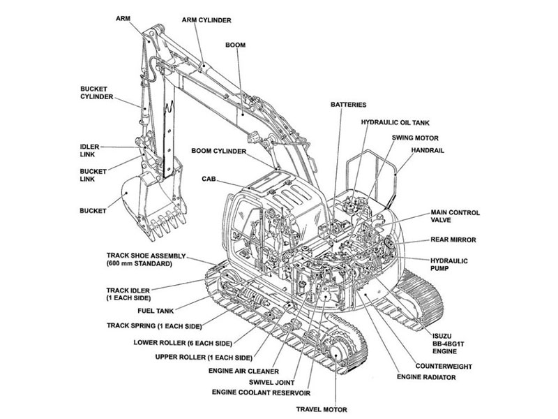

Understanding a hydraulic excavator parts diagram is crucial for maintaining your machine. It helps you identify components and their relationships, making repairs faster and more efficient. Hydraulic schematics provide a clear view of fluid flow, allowing you to pinpoint issues without unnecessary disassembly. This knowledge reduces downtime by streamlining repairs and ensuring proper assembly. You can also detect worn parts early, preventing costly breakdowns. YNF Machinery supports you with high-quality parts and resources, ensuring your excavator operates smoothly and efficiently.
Key Takeaways
Learn hydraulic symbols. Know symbols like pumps and valves to spot parts in diagrams fast.
Use the legend well. Check the legend first to avoid mistakes and assemble parts correctly.
Follow fluid flow step-by-step. Look at arrows to see how fluid moves, helping you fix problems.
Check important parts often. Inspect couplings and seals to stop leaks and keep your excavator working well.
Keep diagrams neat and updated. Save diagrams digitally for quick access and the latest details.
Understanding the Basics of a Hydraulic Excavator Parts Diagram
Decoding Symbols and Legends
Common hydraulic symbols and their meanings
When you look at a hydraulic schematic, the symbols might seem overwhelming at first. These symbols represent the components and flow paths within the hydraulic system. For example, a circle with an arrow inside often indicates a pump, while a rectangle with arrows shows a valve. Cylinders are typically represented by a rectangle with a line through it. Each symbol provides a visual shorthand for understanding how the system operates.
A hydraulic excavator parts diagram often includes key elements such as the boom, arm, bucket, and their respective cylinders. You’ll also find symbols for the hydraulic pump, main control valve, and swing motor. Recognizing these symbols helps you identify the parts and their functions quickly.
How to use the legend to interpret the diagram
The legend acts as your guide to decoding the diagram. It lists all the symbols used and their meanings. Before diving into the schematic, review the legend carefully. Match each symbol on the diagram with its description in the legend. This step ensures you interpret the diagram correctly and avoid mistakes. Misreading symbols or flow paths can lead to incorrect assembly or equipment malfunction.
Layout and Structure of Hydraulic Schematics
System-level vs. component-level views
Hydraulic schematics can be presented at two levels: system-level and component-level. A system-level view shows the entire hydraulic system, including how components like pumps, valves, and cylinders interact. This view helps you understand the overall operation of the machine. In contrast, a component-level view focuses on individual parts, such as the hydraulic pump or a specific valve. Use the system-level view for troubleshooting and the component-level view for detailed repairs.
Understanding the flow of hydraulic systems
Hydraulic systems rely on fluid flow to transmit power. In a schematic, arrows indicate the direction of flow. Start by tracing the flow from the hydraulic pump to the actuators, such as cylinders or motors. Pay attention to valve positions, as they control the flow paths. Ignoring valve states can cause unintended pressure buildup or blocked flow paths. Following the flow step-by-step helps you pinpoint issues and ensures proper assembly during repairs.
Tip: Always check for consistent use of symbols in the diagram. Inconsistent symbols can lead to miscommunication and errors during maintenance.
Key Components in a Hydraulic Excavator Parts Diagram

Hydraulic Pumps and Valves
Identifying pump symbols and their placement
Hydraulic pumps are the heart of an excavator’s hydraulic system. They convert mechanical energy into hydraulic pressure energy, supplying high-pressure oil to various components. On a parts diagram, pumps are often represented by a circle with an arrow pointing outward. You’ll typically find these symbols near the engine, as pumps rely on engine power to operate. Their placement in the diagram shows their connection to other components, such as valves and actuators.
Recognizing valve symbols and their functions
Valves control the flow of hydraulic fluid, ensuring precise movements of the excavator’s attachments. In a diagram, valves are usually depicted as rectangles with arrows or lines indicating flow direction. These symbols help you understand how hydraulic circuits distribute fluid to different parts of the machine. For example, control valves manage the flow to the boom, arm, and bucket cylinders, enabling movements like lifting, digging, and curling. Recognizing these symbols allows you to troubleshoot issues like uneven movements or pressure loss effectively.
Cylinders and Hydraulic Cylinder Seal Kits
How cylinders are represented in diagrams
Cylinders appear as rectangles with a line through the middle in hydraulic schematics. These components convert hydraulic pressure into mechanical force, powering movements like arm extension or bucket rotation. Each cylinder connects to specific parts of the excavator, such as the boom, arm, or bucket. By tracing these symbols, you can identify which cylinder controls a particular function.
The role of Hydraulic Cylinder Seal Kits in preventing leaks
Seal kits play a vital role in maintaining the efficiency of hydraulic cylinders. They prevent fluid leaks, ensuring proper pressure and protecting against contaminants. For instance, the arm cylinder seal kit maintains pressure for smooth arm movement during lifting or digging. Similarly, the bucket cylinder seal kit prevents fluid loss, ensuring efficient operation. These kits also protect internal components from dirt and debris, extending the lifespan of your excavator.
Reservoirs, Filters, and Excavator Couplings
Identifying reservoirs and their connections
Reservoirs store hydraulic fluid and are essential for maintaining system pressure. In diagrams, they are often represented as rectangles or tanks with lines connecting them to pumps and filters. These connections show how fluid flows through the system, ensuring continuous operation. Understanding reservoir placement helps you monitor fluid levels and identify potential issues like air contamination.
The importance of excavator couplings in power transmission
Excavator couplings ensure efficient power transmission between the engine and the hydraulic pump system. They compensate for misalignment and reduce vibrations, protecting the system from damage. In a parts diagram, couplings are typically shown as circular or gear-like symbols between the engine and pump. Recognizing these symbols helps you identify wear and plan maintenance, ensuring smooth operation and minimizing downtime.
Tip: Regularly inspect couplings and seal kits to prevent unexpected failures and maintain optimal performance.
Step-by-Step Guide to Reading a Hydraulic Excavator Parts Diagram

Familiarizing Yourself with the Diagram
Reviewing the legend and layout before starting
Before diving into a hydraulic schematic, take time to review the legend and overall layout. The legend explains the symbols and notations used in the diagram, acting as your key to understanding the hydraulic system. Match each symbol with its description to avoid misinterpretation.
To prepare effectively:
Note Part Numbers and Descriptions: Write down part numbers and their descriptions from the diagram. Include annotations like torque values or material specifications.
Capture Exploded Views and Annotations: Take photos or screenshots of detailed sections. Highlight components you plan to work on.
Record Maintenance Dates and Observations: Log repair dates and note the condition of parts.
Organize Findings by Component or System: Group your notes by systems, such as the hydraulic system or engine.
These steps ensure you approach the diagram with clarity and confidence.
Identifying key sections of the hydraulic schematic
Break the hydraulic schematic into manageable sections. Focus on areas like the pump, valves, and actuators. Identify how these components connect and interact. This approach simplifies the process and helps you locate specific parts quickly.
Identifying Components and Tracing Flow Paths
Cross-referencing symbols with the legend
Use the legend to cross-reference symbols on the diagram. For example, a circle with an arrow represents a pump, while rectangles with arrows indicate valves. This practice ensures you correctly identify each component and its function.
Following the flow from pumps to actuators
Trace the hydraulic fluid’s flow from the pump to the actuators, such as cylinders or motors. Use the following best practices:
Best Practice | Benefit |
|---|---|
Use Standardized Symbols and Templates | Ensures uniformity and clarity, making diagrams easier to interpret across different teams. |
Label Components Clearly | Reduces the risk of misinterpretation by adding labels and flow directions. |
Incorporate Color Coding (Optional) | Improves visual clarity in complex systems by differentiating lines. |
Test and Validate the Diagram | Helps identify errors before implementation through simulation or modeling. |
Update Diagrams with System Changes | Ensures maintenance teams work with the most accurate representation of the system. |
Following these steps helps you understand the hydraulic system’s operation and pinpoint potential issues.
Using the Diagram for Troubleshooting
Pinpointing problem areas in the system
A hydraulic schematic serves as a roadmap for troubleshooting. It helps you identify problem areas by showing the relationships between components.
Understanding hydraulic symbols enhances productivity.
It reduces downtime and ensures system longevity.
A graphical circuit diagram is a road map of the hydraulic system. To a technician skilled in reading and interpreting them, it is a valuable aid in identifying possible causes of a problem. This can save time and money in a troubleshooting situation.
Leveraging diagrams to identify faulty components
Use the diagram to locate faulty components. Start by visually inspecting the system for warning signs like leaks or unusual noises. Then, trace the hydraulic circuit to isolate potential issues. Remember, hydraulic oil follows the path of least resistance, which can guide you in diagnosing pressure-related problems.
By combining visual inspection with the schematic, you can efficiently identify and resolve issues, ensuring your excavator operates smoothly.
Troubleshooting Challenges in Hydraulic Schematics
Ambiguous Symbols and Manufacturer-Specific Notations
How to handle unclear symbols with YNF Machinery’s resources
Hydraulic schematics often include symbols that can confuse even experienced technicians. For example:
Sawtooth lines represent springs but vary based on type.
Circles indicate hydraulic components, with arrows showing fluid flow.
Diamonds identify conditioning devices, such as heat exchangers.
Rectangles denote reservoirs, with shapes indicating pressure levels.
Ovals represent accumulators, while squares depict valves with specific features.
When you encounter unclear symbols, YNF Machinery’s resources can help. Their manuals and guides provide detailed explanations of these symbols. You can also contact their support team for clarification. This ensures you interpret the hydraulic schematic accurately, avoiding costly mistakes during repairs or maintenance.
Using updated manuals for clarification
Manufacturers often use unique notations, which can complicate interpretation. Always rely on updated manuals to understand these notations. YNF Machinery ensures you have access to the latest documentation, tailored to your excavator model. Updated manuals clarify ambiguous symbols and provide insights into manufacturer-specific hydraulic circuits, making your troubleshooting process more efficient.
Misinterpretations and Common Errors
Avoiding mistakes when reading diagrams
Misreading hydraulic schematics can lead to serious issues. Common mistakes include:
Mistake | Impact | Solution |
|---|---|---|
Misreading Symbols or Flow Paths | Incorrect assembly, causing equipment to malfunction or fail. | Double-check each symbol’s function and flow direction by referring to standard symbol charts. |
Overcomplicating Diagrams | Makes troubleshooting and design modifications more challenging. | Use simplified, modular layouts that clearly separate components and functions. |
Ignoring Valve Positions and States | Misinterpreted states can cause unintended pressure buildup. | Always include all valve states to provide a complete operational overview. |
Inconsistent Use of Symbols | Leads to miscommunication and incorrect system assembly. | Use consistent standards throughout the diagram and label the standard used on the drawing. |
Omitting Reservoirs, Filters, or Pilot Lines | Increases the risk of contamination or improper fluid control. | Include all essential components and ensure accurate placement within the system layout. |
Tips for accurate interpretation
To avoid these errors, follow these tips:
Study the legend thoroughly before analyzing the diagram.
Trace the flow paths step-by-step, starting from the pump.
Cross-reference symbols with the legend to confirm their meaning.
Use consistent standards when creating or modifying diagrams.
These practices ensure you interpret hydraulic schematics correctly, reducing downtime and improving repair accuracy.
Outdated or Incomplete Diagrams
The importance of consulting updated resources
Outdated diagrams can lead to misdiagnosis and improper repairs. Hydraulic systems evolve, and older schematics may not reflect current designs. Always consult updated resources to ensure accuracy. Updated diagrams include the latest components and configurations, helping you troubleshoot effectively.
How YNF Machinery ensures access to accurate documentation
YNF Machinery prioritizes providing accurate and up-to-date documentation. Their manuals cover a wide range of excavator models, ensuring compatibility with your machine. By using YNF Machinery’s resources, you gain access to reliable information that simplifies troubleshooting and maintenance. This commitment to accuracy helps you maintain your excavator’s performance and longevity.
Tip: Keep a digital library of updated manuals and schematics for quick access during repairs.
Practical Tips for Effective Diagram Usage
Organizing and Storing Hydraulic Excavator Parts Diagrams
Keeping documentation handy for quick reference
Keeping your hydraulic excavator parts diagrams organized ensures you can access them quickly when needed. Start by grouping diagrams based on the excavator’s systems, such as the hydraulic system or engine. Use labeled binders or folders to store physical copies. For digital storage, consider tools like spreadsheets or maintenance logs. These methods allow you to track part numbers, descriptions, and repair dates efficiently.
Digital tools offer additional benefits. They save time by reducing the need to re-identify parts. You can also prevent errors by ensuring you order the correct components every time. Tracking wear patterns becomes easier, helping you plan preventive maintenance. Sharing diagrams with your team improves collaboration during repairs.
Advantage | Description |
|---|---|
Saves Time | Reduces the need to re-identify parts or revisit diagrams. |
Prevents Errors | Ensures you order the correct components every time. |
Improves Maintenance Planning | Helps you track wear patterns and schedule preventive maintenance. |
Enhances Team Collaboration | Provides a clear reference for other team members working on the same equipment. |
Using digital tools for better management
Digital tools simplify the management of hydraulic diagrams. Use note-taking apps to record part numbers and descriptions. Take photos or screenshots of exploded views and highlight specific components. Maintenance logs help you track repair dates and observations. Organize your findings by system to make future repairs easier.
For example:
Spreadsheets allow you to sort and filter data.
Digital note-taking apps keep your annotations accessible.
Maintenance logs provide a timeline of repairs.
These tools ensure your diagrams remain organized and accessible, reducing downtime during maintenance.
Leveraging YNF Machinery’s Expertise
Accessing manuals, online support, and customer service
YNF Machinery provides extensive support to help you interpret hydraulic diagrams. Their expert guidance simplifies complex layouts, ensuring you understand every symbol and annotation. Interactive diagrams make it easier to visualize the system’s operation. You can also access resources tailored to your excavator model, ensuring accuracy during repairs.
Tip: Contact YNF Machinery’s customer service for assistance with specific diagrams or components. Their team can guide you through troubleshooting and maintenance tasks.
Practicing diagram reading with real-world examples
Practice improves your ability to read hydraulic diagrams. Use real-world examples from YNF Machinery’s resources to enhance your skills. Start by identifying symbols and tracing flow paths in a sample diagram. Compare your findings with the provided explanations to ensure accuracy.
YNF Machinery’s manuals include detailed diagrams and annotations, making them ideal for practice. By familiarizing yourself with these examples, you’ll gain confidence in interpreting diagrams and applying your knowledge during maintenance tasks.
Note: Regular practice helps you identify components faster and troubleshoot issues more effectively.
Applying Diagram Knowledge to Maintenance and Repairs
Diagnosing Hydraulic Issues with Excavator Engine Parts
Using diagrams to identify engine-related problems
Hydraulic diagrams simplify the process of diagnosing engine-related issues. They provide a visual breakdown of components, helping you pinpoint specific parts linked to the problem. By studying the diagram, you can identify the connections between the hydraulic system and the engine. This clarity reduces errors and ensures you focus on the correct components during maintenance. Diagrams also save time by eliminating guesswork, allowing you to address issues efficiently.
Steps for systematic troubleshooting
To troubleshoot hydraulic systems effectively, follow these steps:
Review the hydraulic schematic thoroughly to understand the system’s layout.
Trace the lines on the diagram to locate potential problem areas.
Avoid assumptions and rely on the schematic for accurate diagnosis.
Collect information about recent changes, such as pressure adjustments or part replacements.
Use the schematic to identify issues without disassembling unnecessary parts.
This approach minimizes downtime and ensures precise repairs, keeping your excavator in optimal condition.
Performing Repairs with Hydraulic Cylinder Seal Kits
Identifying parts and their replacements
Hydraulic cylinder seal kits play a crucial role in preventing leaks and maintaining efficiency. Use the diagram to identify the exact seals required for your excavator’s cylinders. Exploded views in the diagram separate the cylinder into individual components, making it easier to locate the seals. Annotations often include part numbers and specifications, ensuring you select the correct replacements.
Ensuring proper reassembly using the diagram
Reassembling a hydraulic cylinder requires precision. Diagrams provide clear instructions and visual representations of each component’s placement. They show the exact position of seals within the cylinder, reducing the risk of misalignment. Annotations may also include torque values for bolts and alignment guidelines for seals. By following the diagram, you can avoid common mistakes like misaligned seals, which can lead to oil leaks and reduced hydraulic efficiency.
Preventive Maintenance with Excavator Couplings
Using diagrams to plan maintenance schedules
Diagrams help you plan preventive maintenance by offering a detailed view of the hydraulic circuits. They allow you to identify components prone to wear, such as couplings. Early detection of worn or damaged parts prevents larger issues and reduces downtime. By understanding the interactions between components, you can schedule maintenance proactively and ensure the excavator operates safely.
Checking for wear and tear in critical components
Excavator couplings are essential for power transmission. Use the diagram to locate these components and inspect them for wear. Regular checks ensure all parts function correctly, reducing the risk of accidents. Diagrams also enhance your understanding of how couplings interact with the hydraulic system, helping you maintain efficiency and extend the lifespan of your equipment.
Tip: Always keep diagrams updated and accessible to streamline maintenance and repairs.
Understanding a hydraulic excavator parts diagram is essential for efficient maintenance and repairs. It helps you avoid common issues like seal misalignment, incorrect assembly, or using incompatible parts. YNF Machinery simplifies your tasks with reliable products like Hydraulic Cylinder Seal Kits and excavator couplings, ensuring smooth operations. Regular practice with diagrams offers long-term benefits: early issue detection, efficient maintenance planning, and enhanced safety. By mastering these diagrams, you can prevent costly downtime and keep your excavator performing at its best.
FAQ
1. How do I find the correct hydraulic cylinder seal kit for my excavator?
Check the part number on your excavator’s cylinder or refer to the hydraulic diagram. Match it with the specifications provided by YNF Machinery. If unsure, contact their support team for assistance.
2. What should I do if the diagram symbols seem unclear?
Refer to the legend included in the diagram. It explains each symbol. For additional help, consult YNF Machinery’s manuals or contact their customer service for clarification.
3. Can I use a hydraulic diagram to troubleshoot leaks?
Yes! Trace the flow paths on the diagram to identify potential problem areas. Focus on seals, couplings, and connections. This method helps you locate leaks without unnecessary disassembly.
4. How often should I inspect excavator couplings?
Inspect couplings during routine maintenance or every 500 operating hours. Look for wear, misalignment, or damage. Use the diagram to locate and check all coupling points.
5. Why is it important to update hydraulic diagrams?
Updated diagrams reflect system changes and new components. Using outdated diagrams can lead to misdiagnosis or incorrect repairs. YNF Machinery ensures you have access to the latest documentation for accurate maintenance.
Tip: Always keep a digital copy of your hydraulic diagrams for quick access during repairs.